Specifying CNC Machined Parts for Robotics (DFM Guide)
How to specify CNC machined robotics parts so they assemble, survive millions of cycles, and stay consistent across batches — wall thickness, tolerances, materials and GD&T.
Robotics for Your Industry
From collaborative robot arms to heavy-payload industrial robots, the parts behind the motion need to be light, strong, dimensionally consistent and delivered on time. We work with robotics OEMs and integrators across North America, Europe and Japan on components that hold up to millions of cycles.
Typical Parts We Make for Robotics Customers
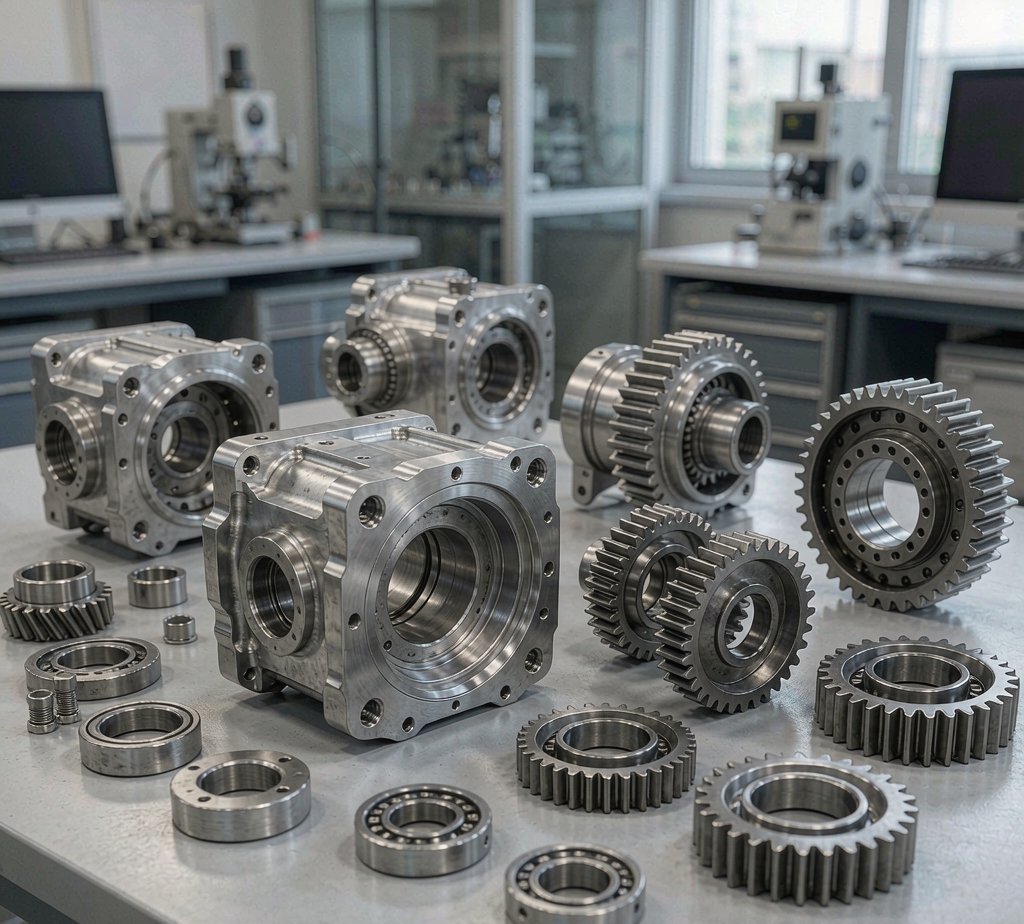
- Robot joint housings and harmonic-drive cases
- End-effector mounting plates and gripper fingers
- Linkages, brackets, and pivot arms
- Reducer housings (RV / cycloidal)
- Cable management brackets and sensor mounts
- Base plates, foundation blocks, and counterweight components
Common Materials and Grades
- Aluminum 6061-T6 — default for housings and brackets
- Aluminum 7075-T6 — for high-stress, weight-sensitive arms
- Stainless 304 / 316 — for food-grade and medical robotics
- Engineering plastics POM / PEEK — for sliders, bushings, cable carriers
Tolerances and Finish Capabilities
| Specification | Capability | Notes |
|---|---|---|
| Standard tolerance | ±0.05 mm | Per ISO 2768-m |
| Precision tolerance | ±0.01 mm | Critical bores, bearing seats |
| Surface roughness | Ra 0.8 µm | Bearing seats and sliding interfaces |
| Anodize / hardcoat | Type II / Type III | For wear and corrosion resistance |
DFM checklist for robotics parts
- Keep wall thickness at or above 1.5 mm where possible; below 1 mm needs special fixturing and a stress-relief cycle between rough and finish.
- Specify bearing seats and wave-generator bores to ±0.01 mm; everything else can run to ISO 2768-m.
- Choose 7075-T7351 over 6061-T6 for high-stress, weight-sensitive arms.
- Call out flatness and position (GD&T) on mounting faces rather than relying on ± dimensions alone.
- Threads in thin aluminum: use inserts or live-tooling threads; avoid tapping thin sections directly.
For the full part-by-part catalog — the materials, thin-wall strategy, bearing-seat tolerances and how each part is machined — see our CNC machined robotics parts page.
FAQ
Frequently Asked Questions
How do you ensure dimensional consistency across batches?
For OEM robotics customers, we lock the fixture and CNC program per part number and run a first-article inspection with CMM at every program launch. Every subsequent batch is checked against the FAI. We also keep your fixture in our store and re-qualify it quarterly.
Can you machine thin-wall aluminum parts without distortion?
Yes. We use special fixturing and roughing strategies to minimize residual stress in thin-wall (1–2mm) parts, and we run a stress-relief cycle between rough and finish machining for critical features. For very thin walls we recommend 7075-T7351 over 6061-T6.
Do you work with harmonic-drive and RV reducer manufacturers?
Yes. We machine housings and flexspline cups for several harmonic-drive and RV-reducer programs. Tolerances on bearing seats and wave-generator bores are typically ±0.01mm.
What wall thickness can you hold on lightweight robot parts?
We typically hold 1.0–1.5 mm walls in aluminium with support fixturing and step-down roughing to avoid chatter. See our robotics parts guide for the full DFM list.
Can you machine bearing seats and harmonic-drive housings to a running fit?
Yes — bearing bores held to ±0.01 mm with in-process probing; we machine the housings our own robots actually use.
Ready to start your project?
Send drawings — get a detailed quote within 24 hours.
Knowledge base: Browse the CNC Machining Knowledge Base