CNC Machined Robotics Parts: Joints, Housings & Components
Robot parts live or die on weight, stiffness and a bearing seat that stays true for millions of cycles. Here is how joint housings, harmonic-drive cases, linkages and end-effector plates are actually machined — materials, thin-wall strategy, and the tolerances that earn their cost. For the industry overview, see our CNC machining for robotics page.
Why Robotics Parts Are Their Own Problem
A robot arm is a stack of rotating and pivoting masses. Every gram on a moving axis is paid for in motor size and cycle time, so the parts behind the motion have to be light and stiff and consistent batch to batch. That is why CNC machined robotics parts — not castings, not prints — carry the joints and housings on most industrial and collaborative robots. The machining is standard; the discipline is in holding thin walls true and bearing seats round.
If your part is still being chosen between processes, the machining vs 3D printing guide shows where each wins.
What Each Robotics Part Is Really Asking For
The part list looks like any precision job — until you see which features decide whether it survives on the arm.
| Part | Why it's tricky | What to spec |
|---|---|---|
| Joint / harmonic-drive housings | Bearing seat must stay round under load | Bore ±0.01 mm, Ra 0.8, finish last |
| End-effector plates & gripper fingers | Stiff, light, true mount pattern | 7075-T6, light anodize |
| Linkages, brackets, pivot arms | Thin wall, no distortion | 7075-T7351, stress-relief cycle |
| Reducer housings (RV / cycloidal) | Tight bores, alignment | 6061/7075, CMM at FAI |
| Sliders, bushings, cable carriers | Low friction, quiet | POM / PEEK inserts |
Materials Quick-Pick
For robotics the material is a weight-and-stiffness decision first. Aluminium 6061-T6 is the default for housings and brackets; 7075-T6 takes over where the part is load-bearing on a moving axis and every gram counts. 316 stainless is the food-grade and medical-robot choice despite the mass. For the non-structural sliding parts inside a joint — bushings, cable carriers, sliders — POM or PEEK cut friction without adding metal. The trade-offs are laid out in our materials overview and the plastic machining guide.
| If the part must… | Start with | Watch out for |
|---|---|---|
| Be a stiff, light housing | Al 7075-T6 | Less corrosion resistance than 6061 |
| Be a stable, cheap bracket | Al 6061-T6 | Don't thin the wall too far |
| Run in food / medical robots | 316 stainless | Weight and slower cycle time |
| Slide quietly inside a joint | POM / PEEK | PEEK holds heat; POM is hygroscopic |
The Tolerances That Earn Their Cost
On a robot part, tight tolerance on a bearing seat pays for itself in joint life. Tight tolerance on a bolt flange is just cost.
| Feature | Hold it to | Why |
|---|---|---|
| Bearing / flexspline seat | ±0.01 mm, Ra 0.8 | Round, true seat = no runout |
| Thin-wall section | 0.02 mm after stress-relief | Stays true, no spring-back |
| Mount pattern (EOAT) | ±0.05 mm | Tool lands where it should |
| General body | ISO 2768-m | General tolerance is enough |
The numeric tables and the tolerance-cost curve are in the CNC tolerance chart; the finish numbers behind that Ra 0.8 seat are in the surface roughness Ra chart, and the GD&T guide covers the symbols that change the quote.
Five DFM Calls That Keep Robot Parts Alive
1. Finish the bearing seat last
The seat that carries the bearing or flexspline is the most important surface on a joint housing. We machine every other feature first, run any stress-relief, then bore and finish that seat as the final operation so nothing downstream can move it. A true, round seat is what keeps runout — and joint life — where it belongs.
2. Stress-relieve thin walls between rough and finish
Thin aluminium wants to move after you remove material. Roughing leaves residual stress; cut the finish pass straight after and the wall springs. A stress-relief cycle between the two passes, plus light roughing passes, is what holds a 1 mm wall to 0.02 mm. For walls under ~1.5 mm we steer customers to 7075-T7351 over 6061-T6.
3. Put the weight where it helps
On a moving axis, thinning a non-critical web saves cycle-time cost in the motor, not just the part. We'll flag a web that can go thinner and a rib that can't, so the arm sheds mass without losing stiffness. This is the single biggest lever on a robot link's real cost.
4. Use plastic for the joint's sliding parts
Bushings, sliders and cable carriers inside a joint don't need to be metal. POM or PEEK there cuts friction and noise and protects the aluminium housing. Grade choice and the quirks of each are in the plastic guide — PEEK holds heat, POM takes on moisture.
5. Lock the program for the program's life
For an OEM robotics part, consistency across batches matters more than the first article. We lock the fixture and program per part number, run a CMM first-article at every launch, and keep your fixture in storage re-qualified quarterly — so a housing machined today matches one from six months ago. Our quality page covers the inspection flow.
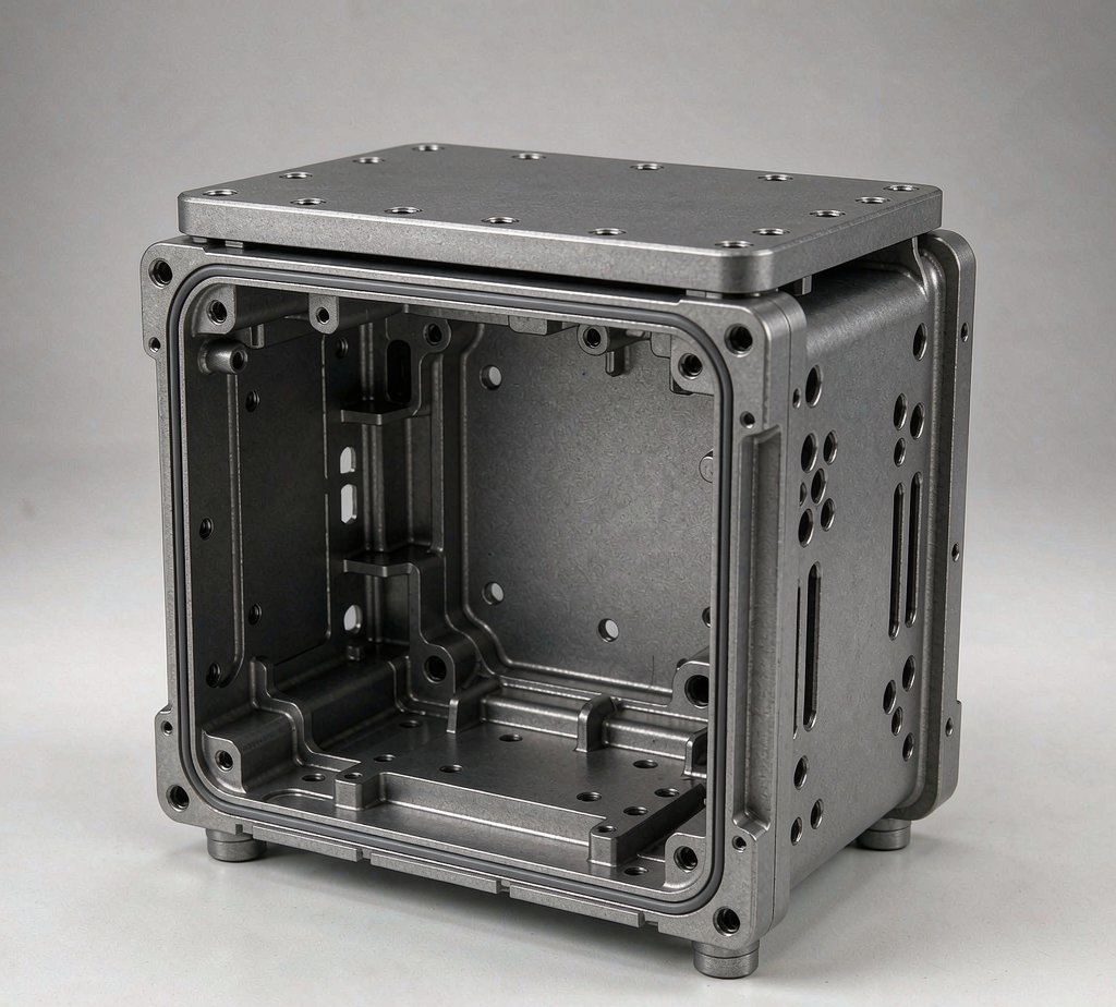
Bearing seat bored and finished last, CMM-checked.
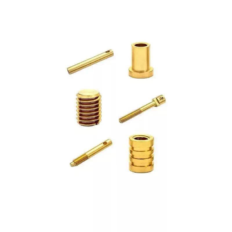
Precision turned components for joints and linkages.
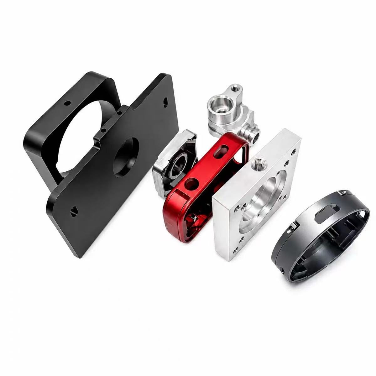
Consistent batches for OEM robotics programs.
Robotics Parts Questions
How thin can you machine an aluminium robot part without distortion?
How do you keep dimensional consistency across robotics batches?
Which material for a lightweight robot arm link?
Do you machine harmonic-drive and reducer housings?
Got a joint housing or arm link that has to survive millions of cycles?
Send the drawing. We'll lock the program for your program's life, finish the bearing seat last, and CMM every first article — consistent batches, true seats.
Related industries: CNC Machining for Automotive · CNC Machining for Aerospace